ClariCalc Pro Structural
This page describes certain ClariCalc Pro features that are of interest mostly to civil and structural engineers. [▼]If you wish to have these features, then you need to (1) buy and install a ClariCalc Pro license, and (2) choose the installation option for Structural.
Beam Diagrams
To solve a continuous beam diagram, start by invoking the Beam command on the Add-Ins ribbon. You'll get a table that looks like this:
| Beam Diagram | |||||||||||||||||||||||
| E (ksi) | I (in4) | Factors | Skip | ||||||||||||||||||||
| Service | ü | ||||||||||||||||||||||
| Span (ft): | |||||||||||||||||||||||
| Node type: | |||||||||||||||||||||||
| Node # | P (kips) | M (k') | |||||||||||||||||||||
| Span # | w (kpf) | ||||||||||||||||||||||
| Loads | Span # | wleft | wright | ||||||||||||||||||||
| Span # | wleft | wright | xstart | xend | |||||||||||||||||||
| Span # | P (kips) | M (k') | xlocal | ||||||||||||||||||||
| Given: | Output detail at xlocal: | ||||||||||||||||||||||
| Span # | xlocal | V | M | Δ | |||||||||||||||||||
Fill in the blanks, then click where it says "Beam Diagram". ClariCalc will analyze the beam and display the loading, shear, bending, and deflection diagrams. The example below shows a two-span continuous beam. ClariCalc has analyzed it with all live load patterns.
| Beam Diagram | ||||||||||||||||
| E (ksi) | I (in4) | Factor | Skip | |||||||||||||
| 29000 | W8x24 | ASCE 7–10 | ü | |||||||||||||
| Span (ft): | 15 | 12 | ||||||||||||||
| Node type | p | p | p | |||||||||||||
| Span # | w (kpf) | |||||||||||||||
| D | all | -wself | ||||||||||||||
| Loads | L | all | -0.30 | |||||||||||||
| Span # | P (kips) | M (k') | xlocal | |||||||||||||
| L | 1 | -2 | 5 | |||||||||||||

Notes
In the "I" cell, write the moment of inertia. If you want to automate that cell, write the section name or a field that reads {Section}. CalcPad will find the Ix of the section.
Click on "Factors" to toggle between Service loads, ASCE 7 load combinations, and NBCC load combinations.
Write the span lengths in line 4.
Node type should be one of: blank, "p", "f", "h", "ph", or "s". ("p" is for pinned, "f" is for fixed, "h" is for hinge, "ph" is for propped hinge, "s" is for spring.)
Sign convention: A negative load is a downward load. Positive is upward. A positive moment is counter-clockwise.
In order to use load combinations, put one of: "D", "L", "E", "W", or "S" in the cell at the left of the load row.
A "span" is a section of beam running from one node to another node. Spans are numbered from left to right.
xstart and xend have the meanings shown in the sketch below.

It's ok to add new load rows. It's ok to delete unused rows, except rows 1, 4, or 5. If you click on the scissors, a macro will automatically delete unused rows.
You can write all
for a span number. A span number can be a list 1,2,3
or 1–3
.
A distributed load can be stretched across more than one span, so
| span # | wleft | wright |
| 1–2 | -0.1 | -0.2 |
means this: 
In the output detail section, "xlocal" is the distance to the nearest leftward node.
If Skip
is checked, ClariCalc will do the analysis with patterned live loads. That is, it will add or withhold live load to each individual span in all possible patterns. It will then display all the patterns that have at least one envelope point.
To get help, click on the question mark.
The utility will erase an existing diagram before drawing a new one.
Concrete Column Interaction Diagrams
To create a Concrete Column Interaction Diagram, start by invoking the Column command on the Add-Ins ribbon. You'll get a table that looks like this:
| Column Diagram | ||
| fc′ | 4 | ksi |
| fy | 60 | ksi |
| ACI 318- | 14 | |
| width | 24 | in. |
| depth | 24 | in. |
| bar size | #8 | 1∕8″ |
| # of bars | 4x4 | |
| clear cover | 2 | in. |
| tie size | #4 | 1∕8″ |
To get a diagram, click on the term Column Diagram
. You’ll get a diagram like the one below.

To get a help screen, click "?".
To toggle between kip-inch and metric units, click "unit".
To toggle the code year between 99 and the current code year, click "318-".
If you delete the ACI 318 line, the macro will work with the current ACI 318.
If you leave depth blank, or delete the depth line, you'll get a round column.
If you replace "width" with "octagon" and delete the depth line, you'll get an octagonal column.
The macro reads the bottom left hand cell to find either "tie" or "spiral."
Lookup Table
ClariCalc Pro extends the ClariCalc Lookup Table to include data for:
- Section properties for every section in the current AISC steel shape database
- Dimension lumber section properties
- Glu-lam beam section properties
- Reinforcing bar section properties (U.S. and Canadian)
- Concrete material properties
- Steel material properties
- Bolt grade material properties
Accessing this information is a two-step process. First, set a Lookup Key by clicking on the button at Add-Ins | Insert | Lookup Key… In the next dialog box, select, say, a section. ClariCalc will insert into your document a note like this one:
Section = “W8x18”
The rest of your document will then inherit all the section properties defined for W8x18
in the Lookup Table. So variables that call for area, flange thickness, etc., will be assigned values from the table. For example:
Aflg = bf tf = (5.25 in)(0.33 in) = 1.73 in²
Ix = 61.9 in⁴; major axis moment of inertia
If a variable’s value is sourced from a Lookup Table, ClariCalc colors it green. That helps a checker to more easily review a document.
If you write another Lookup Key into a location lower in your document, then the first Lookup Key will govern only in the document section between the two keys. You can also over-ride any individual variable assigned by the Lookup Table. As in:
| bf = 4 in | (Over-rides the Lookup Table’s assignment to variable bf . |
You can view the entire Lookup Table by clicking on the button at Add-Ins | Edit | Show | Lookup Table.
Quick Part Entries
The text below describes several Quick Part records that are supplied with the ClariCalc Structural module. To get any of these items in your document, just type the keyword and then hit the  key. Or, select the entry from a list at Add-Ins | Insert | Quick Part…
ClariCalc also runs a ReCalculation on all Quick Part entries. So many of the following items contain a zero as a placeholder for the result to come.
| Keyword | Ab |
| Mnemonic | Area of Bolt |
| Body of entry | Ab = bolt area =\(\frac{\pi d_b^2}4 \) =' 0 in² |
| Keyword | afp |
| Commentary | Area of fireproofing on a steel wide flange beam |
| Body of entry | Afp = (bf + 4″)×(d + 2″) - A =' 0 in² |
| Keyword | Asc | |
| Mnemonic | Area of Steel for Concrete beams | |
| Commentary | Required area of reinforcing steel in a concrete beam. | |
| Prerequisites | fc″ | fc′, in units of psi², instead of psi |
| b | width | |
| d | depth to reinforcement. | |
| fyr | yield stress of reinforcement | |
| Mu | factored bending moment | |
| ρT | max reinf ratio for which ρ may be 0.9 | |
| ρmax | max reinforcement ratio for beams | |
| References | ACI 318, CRSI Report 22 | |
Body of entry
Find required As
xc = parameter for calc below = \(\frac{0.85 f_c' b d}{f_{yr}}\) = 0 =; 0 in²
A1 = \(x_c-\sqrt{x_c^2-\frac{2 x_c M_u}{0.9 d f_{yr}}}\) = 0 =; 0 in²
A2 = per ACI 10.5 = \(\frac{b d\times\max\left((200\text{ psi});3\sqrt{f_c''}\right)}{f_{yr}}\) = 0 =; 0 in²
min As = min(max(A1, A2), 1.33 A1) = 0 =: 0 in²
max As that may use 0.9 for ϕ = b d ρT = 0 =; 0 in²
max As for ductility in beams = b d ρmax = 0 =; 0 in²
| Keyword | asm | |
| Mnemonic | Area of Steel for Masonry | |
| Commentary | Finds the required area of reinforcing steel in masonry undergoing axial load and bending. | |
| Prerequisites | Fsm | allowable stress in steel reinf, psi |
| Fam | allowable axial stress in masonry, psi | |
| Fbm | allowable bending stress in masonry, psi | |
| b, d | width and depth to reinforcement, inches | |
| t | thickness of section, inches | |
| nm | modular ratio = Es/Em | |
| P | service level axial force, kips | |
| M | service level bending moment, k-ft | |
Body of entry
Find minimum As for a masonry section in bending and compression
First, find some constants for use in the calculation:
fa = \(\frac P{b t}\) = psi
xm = \(\frac{3 b d}{2 n_m}\) = 0 = 0 in2
ym = \(\frac M{d F_{sm}}\) = 0 = 0 in2
zm = \(\frac{3 M}{n_m d\left(1-\frac{f_a}{F_{am}}\right)F_{bm}}\) = 0 = 0 in2
For compression,
A1 = \(\frac{5 z_m-3 x_m+\sqrt{\left(3x_m-5z_m\right)^2+8 z_m^2-\frac{8z_m^3}d}}{4-\frac{4 z_m}d}\) = 0 = 0 in2
For tension,
A2 = \(\small\left(x_m+y_m\right)\cos\left(1-3\text{ acos}\left(-\frac{\left(\left(x_m-y_m\right)^3+6 y_m x_m^2\right)}{\left(x_m+y_m\right)^3}\right)\right)-\frac{x_m-y_m}2 \) = 0 = 0 in2
AsMin = max(A1; A2) = 0 = 0 in2
| Keyword | crack | |
| Commentary | Check for cracking in concrete under service loads | |
| Prerequisites | As | area of steel reinforcement |
| b | width of beam | |
| d | depth to reinforcement | |
| nc | modular ratio = Es ÷ Ec | |
| M | service level bending | |
| cc | clear cover to reinforcement | |
| References | ACI 318–05, section 10.6.4 | |
Body of entry
Check cracking per ACI 10.6.4
xn = distance to neutral axis = \(\frac{\sqrt{\left(n_c A_s\right)^2+2 b d n_c A_s}}b \) =' 0 inches
T = chord force = \(\frac M{d-\frac{x_n}3}\) =' 0 kips
fs = \(\frac T{A_s}\) =' 0 ksi
fc = \(\frac T{0.5 b x_n}\) =' 0 ksi
smax = max spacing = \(\min\left(\frac{600\text{kips/in}}{f_s}-2.5 c_c;\frac{480\text{kips/in}}{f_s}\right)\) =' 0 in
| Keyword | defl |
| Commentary | Finds the deflection resulting from uniform loading on a simple beam. |
| Body of entry | Δ = \(\frac{5 M L^2}{48 E I_x}\) =' 0 in; \(\frac L{\Delta}\) = 0 =' 0 |
| Keyword | dev |
| Commentary | Development length for reinforcing bars. |
| Body of entry |
Bar development length per ACI 12.2
ψt = \(\begin{cases}1.3 \text{ if top bar} \\1 \,\,\,\,\text{ otherwise }\end{cases}\) = 1
ψe = \(\small\begin{cases}1.5\text{ if }\text{ epoxy}\text{ coated}\text{ and }\left(\text{cover}\lt 3 d_b\text{ or }\text{ clear}\text{ spacing}\lt 6 d_b\right) \\1.2\text{ for}\text{ all}\text{ other}\text{ epoxy}\text{ coated}\text{ bars} \\1\text{ if }\text{ uncoated}\end{cases}\) = 1
λ = \(\small\begin{cases}1.3\text{ for}\text{ lightweight}\text{ concrete} \\1\text{ otherwise }\end{cases}\) = 1
k1 = \(\small\begin{cases}2\text{ if }\text{ clear}\text{ spacing}\geq d_b\text{ and }\text{ clear}\text{ cover}\geq d_b\text{ and }\text{ stirrups}\text{ or }\text{ ties}\text{ are}\text{ present} \\2\text{ if }\text{ clear}\text{ spacing}\geq 2 d_b\text{ and }\text{ clear}\text{ cover}\geq d_b \\3\text{ otherwise }\end{cases}\) = 2
k2 = \(\small\begin{cases}50\text{ if }d_b\leq(0.75\text{ in}) \\40\text{ otherwise }\end{cases}\) = 40
Ld = \(\max\left(\frac{k_1 f_{yr}\psi_t\psi_e\lambda}{k_2\sqrt{f_c''}}d_b;12\text{ in}\right)\) = 0 = 0 in
| Keyword | Fam | |
| Mnemonic | Fallowable - Masonry | |
| Commentary | Finds the allowable axial stress in a masonry wall. | |
| Prerequisites | r | radius of gyration per UBC table 21-H-1 |
| h′ | height of wall | |
| fm′ | specified 28 day masonry strength | |
| References | 1997 UBC | |
| Body of entry | ||
Fam = \(\begin{cases}\frac{1}{4} f_m'\left(1-\left(\frac{h'}{140 r}\right)^2\right) &\text{ if }\frac{h'}{r}\lt 99 \\\frac{1}{4} f_m'\left(\frac{70 r}{h'}\right)^2 &\text{ otherwise }\end{cases}\) = 0 = 0 psi
| Keyword | Fas | |
| Commentary | ASD allowable axial stress in a steel section. Uses the provisions of AISC 2010 Specification for Structural Steel Buildings. | |
| Prerequisites | Section | Name of the steel section, e.g., W8x18 |
| Fy | Yield stress | |
| kLx | Unbraced length on strong axis | |
| kLy | Unbraced length on weak axis | |
| Body of entry | Fa = Fas(Section; Fy; kLx; kLy) =' 0 ksi | |
| Keyword | fb | |
| Commentary | Bending stress in a beam. | |
| Prerequisites | M | bending moment |
| Sx | section modulus of beam | |
| Body of entry | fb = \(\frac{M}{S_x}\) =' 0 ksi | |
| Keyword | fby |
| Mnemonic | Fbending on Y axis |
| Commentary | Finds the minor axis bending stress in a beam. |
| Body of entry | fby = \(\frac{M_y}{S_y}\) =' 0 ksi |
| Keyword | f'c or fc' |
| Commentary | A quick way to get fc′ well formatted. |
| Body of entry | It enters as f_c′, then builds up to fc′ during calculation. |
| Keyword | fm | |
| Commentary | Bending stress in masonry due to axial load & bending. Note: This one is not well checked. | |
| Prerequisites | As | area of reinforcing steel |
| b | width of section | |
| d | depth to reinforcement | |
| P | service level axial force | |
| M | service level bending | |
| Body of entry | ||
ρ = \(\frac{A_s}{b d}\) = 0 = 0
k = \(\sqrt{\left(n_m\rho\right)^2+2 n_m\rho}-n_m\rho \) = 0 = 0
tf = unit wall thickness = 1.25 in
kd = k d = 0 = 0 in
C = chord force = \(\begin{cases}\frac M{\left(1-\frac k 3\right)d} &\text{ if } kd \lt t_f \\\frac M{d-t_f} &\text{ otherwise }\end{cases}\) = 0 = 0 kips
fb = \(\begin{cases}\frac{2 C}{b kd} &\text{ if } kd \lt t_f \\\frac{2 C}{\left(1+kd-\frac{t_f}{kd}\right)b t_f} &\text{ otherwise } \end{cases}\) = 0 = 0 psi
fa = \(\frac P{b t}\) = 0 = 0 psi
interaction = \(\frac{f_a}{F_{am}}+\frac{f_b}{F_{bm}}\) = 0 = 0
fs = \(\frac C{A_s}\) = 0 = 0 ksi
| Keyword | fvs | |
| Commentary | Finds the shear stress in a steel beam. | |
| Prerequisites | V | shear in beam |
| d | depth of beam | |
| tw | thickness of web | |
| Body of entry | fv = \(\frac V{d t_w}\) =' 0 ksi | |
| Keyword | hook |
| Commentary | Writes out the provisions of ACI 12.5. You have to review all the coefficients before you run the calculation. |
| Body of entry |
Check hooked bar development length, from ACI 12.5
db = 0.625 in
ψe = \(\begin{cases}1.2 &\text{ if epoxy coated} \\1 &\text{ otherwise }\end{cases}\) = 1
λ = \(\begin{cases}0.75 &\text{ if lightweight concrete} \\1 &\text{ otherwise }\end{cases}\) = 1
k1 = \(\begin{cases}0.7 &\text{ if side cover} \geq 2.5'' \text{ and cover past hook} \geq 3'' \\1 &\text{ otherwise }\end{cases}\) = 1
k2 = \(\begin{cases} 0.8 &\text{ if bar is within ties spaced }\leq 3 d_b \\ 1 &\text{ otherwise } \end{cases}\) = 1
k3 = \(\min\left(\frac{A_{sRequired}}{A_{sProvided}};1\right)\) = 1; (conservative, but fast)
Ldh = \(\max \left(8 d_b;\, 6\text{ in; } \frac{0.02 \psi_e k_1 k_2 k_3 f_{yr}}{\lambda \sqrt{f_c''}}d_b\right)\) = 0 = 0 inches
| Keyword | Icr |
| Commentary | Cracked moment of inertia of a concrete beam. |
| References | Wang and Salmon, Reinforced Concrete Design |
| Body of entry |
xn = distance to neutral axis = \(\frac{\sqrt{\left(n_c A_s\right)^2+2 b d n_c A_s}-n_c A_s}b \) =' 0 inches
Icr = cracked moment of inertia = \(\frac 1 3 b x_n^3+n_c A_s\left(d-x_n\right)^2\) =' 0 in⁴
| Keyword | inter |
| Mnemonic | interaction |
| References | AISC 341–05 |
| Body of entry |
interaction = \(\begin{cases}\frac{P_u}{\mathrm{\phi}P_n}+\frac{8 M_u}{9\mathrm{\phi }M_n}\text{ if }\frac{P_u}{\mathrm{\phi}P_n}\geq 0.2 \\\frac{P_u}{2\mathrm{\phi}P_n}+\frac{M_u}{\mathrm{\phi}M_n}\text{ otherwise }\end{cases}\) =' 0 ≤ 1.0
| Keyword | Ix |
| Mnemonic | Ix = moment of inertia on major axis |
| Commentary | Section properties of a built-up section. |
| Body of entry: |
Find section properties of built up section
| Region | y | A | A y | A(y-\(\bar y\))2 | Iself | Q |
|---|---|---|---|---|---|---|
| W8x31 | 4.5 | 18 | 81 | 8.6 | 110 | -12.42 |
| coverPlate | -0.25 | 2 | -0.5 | 59.2 | 5 | -10.88 |
| 3 | 11.8 | 3.54 | 41.77 | 154.7 | 110 | 23.4 |
| Sum | 23.54 | 122.27 | 222.5 | 225. | 0.1 | |
| \(\bar y = \frac{\Sigma(A y)}{\Sigma A}=\) | 5.19 | Ix = 448 | ||||
| Keyword | lap or splice |
| Commentary | Lap splice length for reinforcing bars. |
| Body of entry | Lsplice = max(1.3 Ld; 12″) = 0 =; 0 in |
| Keyword | M |
| Commentary | Bending in a simple beam with a uniform line load. |
| Body of entry | M = \(\frac{w L^2}8 \) =' 0 k·ft |
| Keyword | Mas |
| Commentary | ASD allowable bending moment in a steel section. Uses the provisions of AISC 2010 Specification for Structural Steel Buildings. |
| Body of entry |
Mallowable = \(\frac{M_n}{\mathrm{\Omega }}\) = Mas(Section; Fy; Cb; Lb; x-axis
) =' 0 k·ft
| Keyword | Materials |
| Commentary | Inserts information for design. |
| Body of entry |
Materials
Steel
Fy = yield of structural steel of channels, angles, and A36 plates = 36 ksi
Fy = yield of structural steel of wide flange sections and A572 Gr 50 plates = 50 ksi
E = modulus of elasticity = 29,000 ksi
G = shear modulus of elasticity = 11,200 ksi
Cb = 1 (default for beams)
Concrete
fc′ = specified 28 day compressive strength = 4500 psi
fc″ = fc′ = 4,500 psi²
fyr = yield of reinforcing steel = 60,000 psi
β1 = \(\begin{cases}0.85 &\text{ if }f_c'\leq 4000 \\0.65 &\text{ if }f_c'\geq 8000 \\0.85-\frac{\left(f_c' -4000\right)}{20{,}000} &\text{ otherwise }\end{cases}\) = 0= 0
ρT = \(\frac{0.85\beta_1 f_c'}{f_{yr}}\times\frac{0.003}{0.003+0.005}\) = 0 = 0
ρmax = \(\frac{0.85\beta_1 f_c'}{f_{yr}}\times\frac{0.003}{0.003+0.004}\) = 0 = 0
Ec = concrete modulus of elasticity = 57\(\sqrt{f_c''}\) = 0 = 0 ksi
Gc = shear modulus of elasticity = \(\frac{E_c}{2\times(1+1.021)}\) = 0 = 0 ksi
nc =\(\frac E{E_c}\) = 0 = 0
| Keyword | Masonry |
Body of entry
Masonry
Concrete masonry unit specified strength = 1900 psi.
Type M or S mortar.
Per UBC table 21-D, full fm' is:
fm' = 1500 psi
Em = 750 fm' = 0 =; 0 ksi
Gm = 0.4 Em = 0 =; 0 ksi
nm = E/Em = 0 =; 0
No special inspection, so use half stresses for working stress design and analysis:
fm' = fm'/2 = 0 =; 0 psi
Allowable bending stress:
Fbm = 0.33 fm' = 0 =; 0 psi
Allowable bearing stress
Normal Fbrm = 0.26 fm' = 0 =; 0 psi
If bearing is on < 1/3 of element, Fbrm = 0.38 fm' = 0 =; 0 psi
Allowable shear stress:
In bending members
Where no shear reinforcement exists,
Fvm = fm'^0.5 = 0 =; 0 psi
Where shear reinforcement takes all shear:
Fvmr = 3 fm'^0.5 = 0 =; 0 psi
In shear walls
see analysis
Allowable stresses in reinforcement
Fsm = 24000 psi
Units will be nominally inches wide and they'll be grouted at " o.c., so:
r = radius of gyration per UBC table 21-H-1 = INSERT VALUE HERE in
| Keyword | Mc | |
| Commentary | Bending strength of a concrete beam. | |
| Prerequisites | As | area of steel reinforcement |
| fyr | yield stress of steel reinforcement | |
| fc' | specified strength of concrete | |
| b | width of beam | |
| d | depth to reinforcement | |
| Body of entry | ||
a = \(\frac{A_s f_{yr}}{0.85 f_c' b}\) =' 0 inches
ϕMn = \(0.9 A_s f_{yr}\left(d-\frac a 2\right)\) =' 0 k·ft
| Keyword | Ms |
| Commentary | LRFD allowable bending moment in a steel section. Uses the provisions of AISC 2005 Specification for Structural Steel Buildings. |
| Body of entry |
ϕMn = Ms(Section, Fy, Cb, Lb, x-axis
) =' 0 k·ft
| Keyword | nr |
| Mnemonic | number required |
| Commentary | Finds the number of 1∕16's required in a fillet weld. |
| Prerequisites | f: line load on weld, kips/inch, strength level |
| References | AISC Manual of Steel Construction, 9th Edition |
| fv = \(\frac f{A_{weld}}\) < (0.75)(0.6) FEXX
So, Nr = \(\frac{0.75\times 0.6\times 70}{16\times\sqrt 2}\) = 1.392 |
Body of entry
Nr = required number of 1∕16's in fillet weld = \(\frac f{1.392}\) =' 0
| Keyword | Pas | |
| Commentary | ASD allowable axial force in a steel section. Uses the provisions of AISC 2005 Specification for Structural Steel Buildings. | |
| Prerequisites | Section | Name of the steel section, e.g., W8x18 |
| Fy | Yield stress | |
| kLx | Unbraced length on strong axis | |
| kLy | Unbraced length on weak axis | |
| Body of entry | ||
Pallowable = \(\frac{P_n}{\mathrm{\Omega }}\) = Pas(Section; Fy; kLx; kLy) =' 0 kips
| Keyword | Ps | |
| Commentary | LRFD allowable axial force in a steel section. Uses the provisions of AISC 2005 Specification for Structural Steel Buildings. | |
| Prerequisites | Section | Name of the steel section, e.g., W8x18 |
| Fy | Yield stress | |
| kLx | Unbraced length on strong axis | |
| kLy | Unbraced length on weak axis | |
| Body of entry | ϕPn = Ps(Section; Fy; kLx; kLy) =' 0 kips | |
| Keyword | Seismic distribution |
| Commentary | Vertical distribution of seismic base shear. |
| Prerequisites | Vbase, k, Ta |
| References | ASCE 7 section 12.8.3 |
| Body of entry: |
Vertical distribution of seismic force by equivalent lateral force procedure
k = \(\begin{cases}1 &\text{ if }T\leq 0.5 \\2 &\text{ if }T\geq 2.5 \\1+0.5(T-0.5) &\text{ otherwise }\end{cases}\) = 1.0
Fi = shear at level i = \(\frac{W_\text{i}h_\text i ^k}{\sum{\left(W\,h^k\right)}}V\)
| Level | height | weight | W hk | F |
|---|---|---|---|---|
| 4 | 58 | 91 | 0 | 0.0 |
| 3 | 45 | 80 | 0 | 0.0 |
| 2 | 31 | 70 | 0 | 0.0 |
| 1 | 15 | 108 | 0 | 0.0 |
| Sum | 349 | 0 | 0.0 |
| Keyword | shearwall | |
| Commentary | Shear wall stiffness, for rigid diaphragm analysis. | |
| Prerequisites | Eshearwall | modulus of elasticity |
| Gshearwall | shear modulus | |
| Body of entry | ||
Find shear wall stiffnesses
Eshearwall = Ec = 3120 ksi
Gshearwall = Gc= 1290 ksi
R = \(\frac V{\Delta}\) = \(\frac 1{\frac{H^3}{3 I E_{s\mathrm h earwall}}+\frac{1.2 H}{A G_{s\mathrm h earwall}}}\)
| Wall or wall section | H | L | teff | A | I | R |
|---|---|---|---|---|---|---|
| ft | ft | in | ft² | ft⁴ | kips/in | |
| 1 | 12 | 34 | 8 | 22.7 | 2,184 | 20,823 |
| 2 | 12.5 | 10 | 8 | 6.7 | 56 | 2,197 |
| 3 | 12 | 21.33 | 8 | 14.2 | 539 | 10,632 |
| 4 | 12.5 | 30 | 8 | 20. | 1,500 | 16,655 |
| Keyword | soil | |
| Commentary | Finds the soil pressure under an isolated rectangular foundation. | |
| Prerequisites | Ptotal | Downward force on foundation |
| A | area of foundation | |
| Mot | Overturning moment on foundation | |
| B | width of foundation | |
| L | length of foundation | |
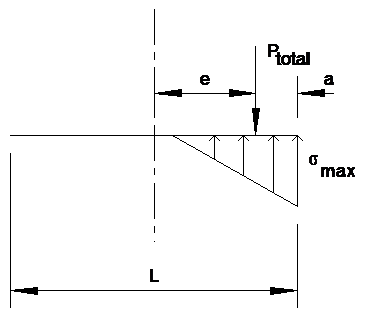
Body of entry
σnormal = \(\frac{P_{total}}A \) = 0 = 0 ksf
e = \(\frac{M_{ot}}{P_{total}}\) = 0 = 0 feet
a = \(\frac L 2 -e\) = 0 = 0 feet
σmax = \(\frac{2 P_{total}}{3 B a}\) = 0 = 0 ksf
| Keyword | Vc |
| Commentary | Shear strength of a concrete beam |
| References | ACI 318–10 |
| Body of entry | ϕVc = \((0.75)(2)\sqrt{f_ c''} b d\) =' 0 kips |
| Keyword | Vs |
| Commentary | Shear strength of a steel wide flange beam |
| References | AISC 360–10 section G |
| Body of entry | ϕVn = (0.9)(0.6) Fy d tw =' 0 kips > Vu, |